PDF: Stanadyne DB2 and DB4 retained drive shaft removal and install
Removal
All Stanadyne DB4 and most DB2 injection pumps will have a retained drive shaft (shaft stays in the pump when the pump is removed from the engine).
Clean the exterior of the injection pump and mounting surfaces.
IMPORTANT: Never steam clean or pour cold water on an Injection pump while the pump is running or while it is warm. To do so may cause seizure of the injection pump.
- Disconnect shut-off cable and speed control linkage, if equipped.
- Disconnect electrical connection to shut-off solenoid or throttle positioning solenoid, if equipped. Disconnect the cold start switch, if equipped. Tag electrical wires for correct reassembly.
- Disconnect all high pressure injection lines
IMPORTANT: ALWAYS use a backup wrench when loosening or tightening fuel lines at the injection pump so that discharge fittings are not altered to prevent possible internal pump damage.
- Disconnect fuel return line and fuel supply line.
- Remove injection pump drive gear cover.
- Remove injection pump drive gear cover (shown removed). Remove drive gear retaining nut and washer from end of pump shaft. Be careful not to let the washer fall inside the timing gear cover.
NOTE: The injection pump drive gear fits snugly onto a tapered drive shaft and is indexed by a hollow pin or Woodruff key installed in the drive shaft.
- Use a gear puller to remove the drive gear from the tapered shaft. Use care not to damage the end of the injection pump drive shaft.
Housing Timed Injection Pumps:
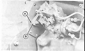
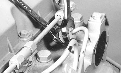
Check to make sure marks are present, and lined up, on both the pump mounting flange (B) and on the front cover (A). If the timing mark is not clearly visible, scribe a line on the front cover that matches the timing line on the injection pump.
- Remove the injection pump mounting nuts and remove the injection pump from the mounting studs.
Inspection
- Inspect injection pump mounting hole in cylinder block, making sure it is clean and free of burrs.
- Inspect the pump mounting surface, making sure that it is clean and smooth and free of burrs.
- Inspect injection pump drive shaft for presence of metal transfer from gear slippage. Also, check to see that the index pin in the shaft is not damaged, indicating gear slippage.
- If the shaft shows signs of gear slippage, the injection pump is very likely seized, and the cause of the seizure must be found before reinstalling a repaired or replaced pump. The drive gear must also be changed
Installation
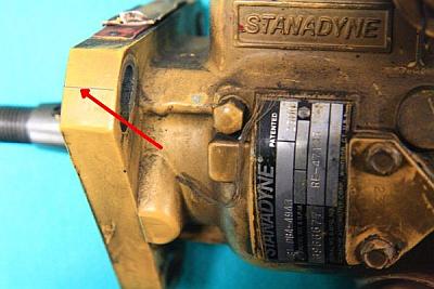
Injection pump mounting flange timing mark (B) and front plate timing mark (A) presence and alignment MUST BE verified before removing pumps from engine, when the pump is reinstalled on engine, time pump by aligning these two (external) marks. DO NOT reference internal timing marks (on pump cam ring and governor weight retainer) for accurate pump timing.
- Install seal into groove on front face of pump mounting flange. Slide injection pump onto mounting studs while inserting pump shaft into drive gear.
- Check pump shaft and index pin for proper alignment with pump drive gear key slot.
IMPORTANT: Shaft roll pin may be easily damaged if improperly assembled. Pump drive gear should not move when initially installing pump index pin into drive gear key slot.
- The pump should sit squarely and solidly on the mounting pad when a slight pressure is applied.
IMPORTANT: DO NOT use tightening force of pump mounting stud nuts to pull pump shaft into drive gear
- With the pump shaft index pin properly engaged in the drive gear key slot, finger-tighten mounting stud nuts.
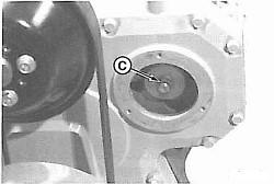
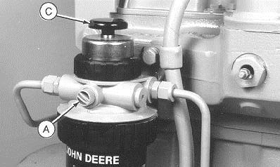
- Push pump drive gear firmly onto shaft taper. Install washer and retaining nut (C) onto end of shaft. Tighten the retaining nut to the specified torque, per your engine service manual. Install access cover plate using a new O-ring, if needed.
- Align timing mark on pump flange with timing mark on front plate.
- Tighten the mounting nuts/bolts securely.
- Then install the injection lines, but leave the injector ends loose.
- Reconnect the fuel inlet and return line, leaving the inlet line loose for bleeding procedures.
- Reconnect the shutoff solenoid (if equipped)
- Reconnect the throttle linkage.
Priming and Starting
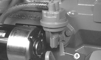
- Open the bleeder screw on the secondary filter (if equipped) and operate the hand primer to bleed the air from the system.
- When fuel flows freely from the fuel inlet line, tighten the fuel inlet line at the injection pump.
- Leave the shut-off disconnected or in the off position and crank the engine over for 10 seconds.
- Connect the electrical shut-off solenoid.
- Crank the engine to start, with ONLY ONE INJECTION LINE LOOSE. Leaving more than one line open at a time, while cranking, can cause an air lock.
- Crank the engine over until fuel, free of bubbles, flows from the injector, tighten the injection line.
- Repeat for the next line, until the engine starts.
Use two open-ended wrenches if needed. You can experience an airlock while trying to bleed the fuel system if all the injection lines are loose at one time while cranking the engine.