REMOVAL; INTERNATIONAL TRACTOR
PDF: Bosch VA Pump, International Installation Instructions
Clean the left side of the engine to prevent dirt entering the injection pump when the fuel lines and injection lines are removed. Shut off the fuel supply from the fuel tank.
You will need to remove the plate on the front of the timing gear cover directly in front of the injection pump. This plate has four studs with nuts one (the lower left) can be seen in the photo below, it is directly above the timing pointer. Clean the cover area before you remove the plate to prevent dirt into the engine. Once this plate is removed you will see the gear that drives the pump. At the center it will have a hub with 3 small bolts and a larger nut in the center on the threaded end of the pump drive shaft. DO NOT loosen the three small bolts.
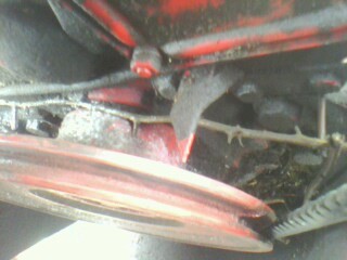
Now align the pointer in the picture above with degree mark for your engine, most of the 3-cylinder engines will be at 14 degrees, some 4-cylinder engines may be different. Verify proper timing specification in your engine service manual, timing can vary between engines from 8 to 18 degrees. Some engines have the timing marks on the flywheel.
As you are approaching the degree mark for your engine, remove the timing cover on the side of the injection pump. If you are on the compression stroke you should see a line on the cam plate above the pointer that is near the center of window.
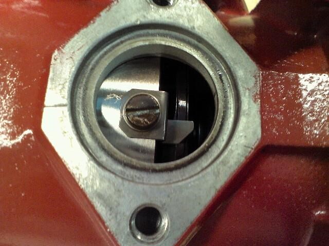
This line can be faint and may be hard to see. If there is no line visible rotate the engine one complete revolution. Stop the engine rotation as the mark reaches the pointer and observe the timing pointer to the front pulley, as outlined in Picture 1. If it is on the correct degree mark for your engine, then the engine is correctly timed.
Then remove all the lines and linkages from the pump, leave the levers installed on the injection pump. Remove the center larger nut and washer at the gear leaving the 3 smaller bolts tight. Now replace the larger nut without the washer leaving the nut flush with the end of the pump drive shaft, taking extreme measures not to drop anything into the timing gear cover. Loosen the mounting bolts on the pump side from the pump.
If you do not have the correct puller you can use a soft punch made from aluminum or brass to strike the nut, that you returned to the end of the pump drive shaft. One quick hard strike should release the tapered shaft from the gear. Be careful not to lose the driveshaft key when you remove the pump from the engine.
DO NOT crank the engine over after the pump has been removed. The pump drive gear will break the front cover
INSTALLATION
Lining the pump key up with the key way in the gear may be a challenge. The pump when it is on the timing mark will be on its so-called compression stroke and it may not stay where you want it. Use one of the following 2 methods.
1) If you are certain you had it on the mark when it was removed, loosen the 3 smaller bolts and rotate the center hub of the gear to line up the key. Once the pump shaft is secured in the key way replace the center nut, then replace the mounting bolts of the pump. Then place a socket on the center nut to rotate the pump shaft to re-align the timing marks in the side window as they were when you removed the pump. When your timing marks in the window of the pump are in line, tighten the three smaller bolts in the gear hub.
2) You can also rotate the engine back a few degrees to line the key in the pump up with the gear. The engine will not need to move much usually this can be done with the fan or a socket on one of the bolts that holds the front pulley on. After the pump is secured to the engine and the center nut is tight. Back the engine up a few degrees more to remove any free play in the timing gears. Then bring the engine back to the target degree mark and check the pointer in the window. If it is not in line, rotate the pump housing to line the mark up, (loosen the outer pump mounting bolts).
Now replace the lines and linkages, if the injector lines were not removed at the injector you may be able to bleed the air out from the injector lines at the pump, if they were removed from the injector you will need to leave them loose until the air is out.
One thing to note; these units have no supply pump and rely on gravity to supply fuel to the pump. When installing a VA pump you must be sure the fuel in the tank is higher than the pump. Turn the fuel on before tightening the inlet line and be sure you have a flow of fuel at the pump before you tighten the inlet. Some pumps you can leave the return loose until fuel come out of it also.
You will need to check your low idle speed and adjust it if it is out of range. The stop screw nearest the front of the engine controls the low idle.
