Removal
PDF: Bosch Inline Pump – John Deere Pin Timed
- Clean injection lines and area around the injection pump with cleaning solvent or a steam cleaner.
- Rotate engine flywheel (in normal running direction) until No.1 piston is at “TDC” (top dead center) compression stroke. At this point, John Deere JOE81-4 timing pin should enter hole in flywheel.
IMPORTANT: Never steam clean or pour cold water on an Injection pump while the pump is running or while it is warm. To do so may cause damage to the injection pump.
- Remove injection pump drive gear cover and O-ring.
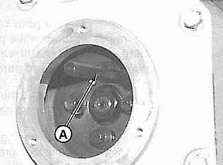
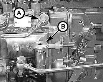
- Install JDG886 Injection Pump Timing Pin (A) through injection pump drive gear into injection pump hub until it bottoms. In some instances, it may be necessary to rotate the pump drive hub slightly to get the pin installed.

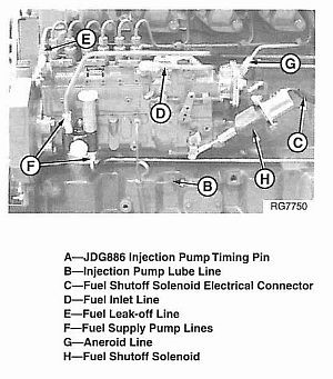
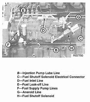
- Disconnect injection pump lube line (B).
- Disconnect fuel shutoff solenoid electrical connector (C).
- Remove fuel inlet line (D). Remove fuel leak-off line (E).
- Disconnect fuel supply pump lines (F).
- Disconnect aneroid line (G).
- Remove fuel injection line nuts (A).
- Remove four injection pump drive gear cap screws (C).
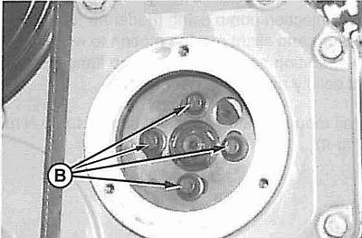
- Remove four mounting stud nuts (8) which secure injection pump to cylinder block.
- Carefully remove injection pump from mounting studs and place it on a clean flat surface.
Installation
If engine was rotated after injection pump was removed, rotate flywheel until JDE81-4 Timing Pin enters flywheel at No.1 cylinder’s “TDC” compression stroke.
1. When No. 1 cylinder is at ‘TDG” compression stroke, intake and exhaust valves for No. 1 cylinder will be closed and both rocker arms will be loose.
2. Rotate injection pump drive hub until marks on drive hub (B) and pointer (A) are aligned.
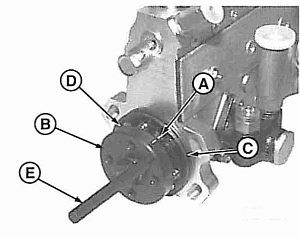
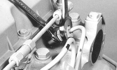
NOTE: It may be necessary to rotate pump hub slightly to allow JDG886 Injection Pump Timing Pin (E) to enter bearing plate.
3. Thread JDG886 Timing Pin into drive hub as shown, and tighten until it bottoms against bearing plate (D).
4. Install a new O-ring (C) on bearing plate. Lightly lubricate O-ring with engine oil to aid in pump installation and prevent O-ring damage.
5. Install injection pump using moderate forward pressure and slight rocking motion to work O-ring into mounting bore. Injection pump flange should seat solidly against cylinder block.
6. Install mounting stud nuts and tighten to 70 N·m (52 Ib-ft).
7. Carefully install drive gear on pump drive hub, position gear so mounting cap screws are approximately centered in mounting slots. This will allow for minor adjustment of pump timing, should the need arise.
8. Install drive gear-to-pump hubcap screws (B) and tighten to 47 N’m (35 Ib-ft).
9. Remove JDG886 Injection Pump Timing Pin (A) from injection pump hub.
10. Install injection pump drive gear cover using a new O-ring, if needed. Tighten cap screws to 27 N’m (20 lb-ft). 11. Connect fuel delivery lines. Tighten line nuts to 27 N’m (20 Ib-ft).
IMPORTANT: DO NOT move delivery valve fittings while tightening line nuts. If delivery valve and barrel housing rotates while tightening a fuel line nut, the rack may bind inside the injection pump and regulation or fuel delivery may be altered.
12. Connect aneroid line (G). 13. Connect fuel supply pump lines (F). 14. Connect fuel inlet line (D) and leak-off line (E). 15. Connect injection pump oil line (B) to cylinder block fitting. 16. Connect fuel shutoff solenoid connector. 17. Remove oil fill plug (arrow) from governor housing and add 0.5 pint (0.24 liters) of clean engine oil.
Priming and Starting
- Loosen fuel return line (A).
- Unscrew hand primer (B) on fuel supply pump until it can be pulled by hand.
- Operate the hand primer until fuel flow is free from air bubbles.
- Simultaneously stroke the hand primer down and close the fuel return port. This prevents air from entering the system. Tighten securely.
- Lock hand primer in position.
- Connect throttle levers and adjust for full travel as required.
- Crank the engine to start.
- If the engine will not start, loosen the injection lines at the injectors, one line at a time. Crank the engine over until fuel free of bubbles flows from the injector, tighten the injection line.
| Use two open ended wrenches if needed. |
